Rise in pressure
As we have seen, to increase the thrust, you must either increase the surface area of the nozzle or increase the pressure.
You should first know that the soft drink bottles are designed to hold 10 bars. Several water rocket enthusiasts have tested the limit on bottles and all of them reach an explosion pressure of around 13 bars.
In addition, bicycle pumps or electric compressors are hardly capable of going beyond 8 to 10 bars.
So to go further, we will have to find a tank capable of withstanding higher pressures, while being very light and a pressurizing system capable of providing the desired pressure.
Finally, it will be necessary to ensure that the launcher is also able to withstand the pressure and that the retaining system will withstand the stresses generated by the maximum pressure.
The thruster
Beyond 10 bars, you'll have to forget about PET bottles. What immediately comes to mind is to use a composite tank: fiberglass or carbon or Kevlar or any combination of these three, impregnated with epoxy resin.
I made a number of attempts that I describe to you below.
First attempt:
The tank is constructed from a 42mm diameter and 1172mm long polycarbonate tube reinforced with a carbon braid coated with epoxy resin. The bottom and the nozzle are also made of polycarbonate partially covered with carbon. Pressure resistance tests were carried out on test tubes manufactured in an identical manner. The first tests resulted in leaks from around 20 bars, which led to modifications in the manufacture of the ends and above all in the gluing of these.
Manufacture of the test tube
|
|
|
|
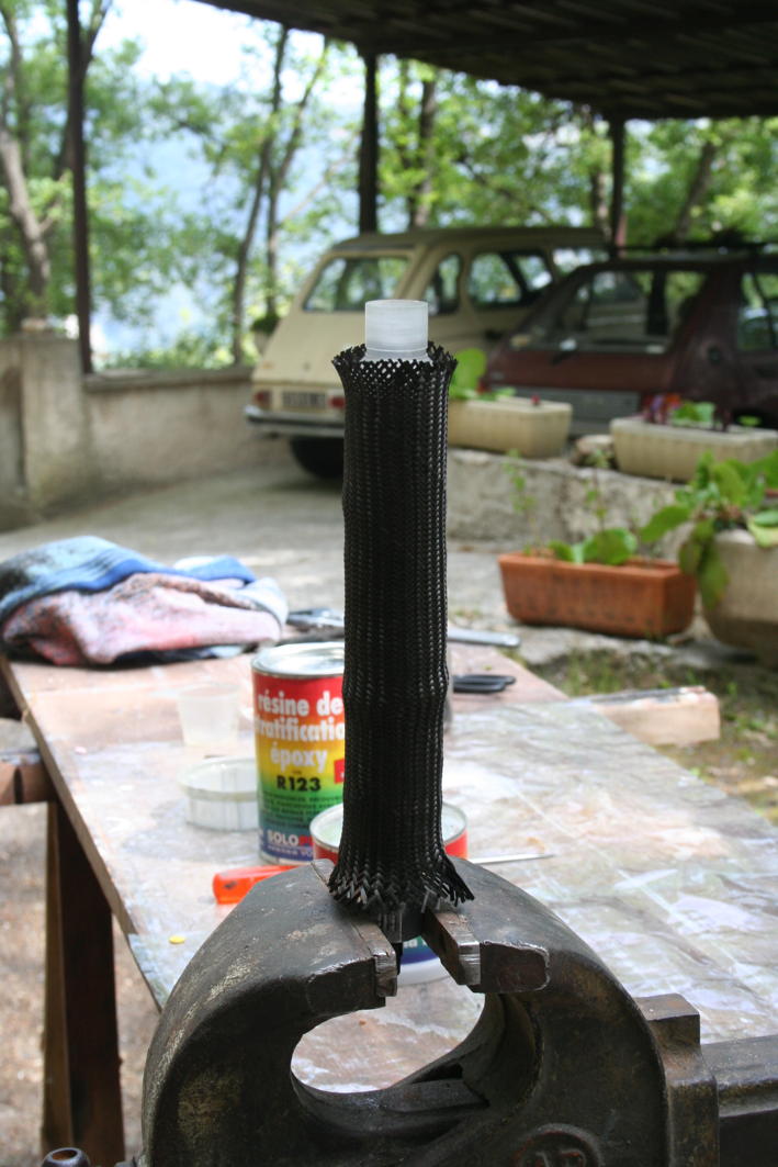
First a polycarbonate tube with its 2 machined ends in polycarbonate round then glued with Sycaflex 11FC |
On this set, we slide a carbon fabric sheath that we are going to coat with epoxy resin |
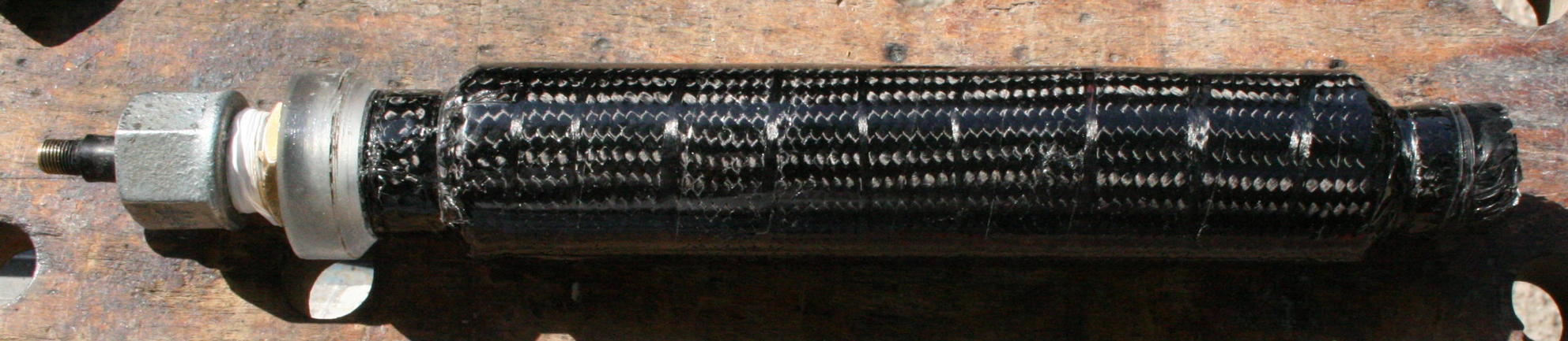
The finished tube after drying for 24 hours |
The last tests made it possible to rise up to 40 bars, without problem, then up to 56 bars (limit of the test pump) and at this pressure micro-leaks appeared.
The manufacture of the final tank was done according to the same process, namely: manufacturing the nozzle and the top cap in polycarbonate round, then gluing them in an FTC T2 tube (42mm in diameter and 1172mm long). Bonding made with Sykaflex 11FC and Methylene chloride. Sikaflex for sealing was applied most inside the tube, while methylene chloride was applied to the 2 cm closest to the edge of the tube. The methylene chloride being a polycarbonate dissolver, it makes a weld between the two parts in contact, which is really very strong. But this solvent being excessively volatile, it is difficult to have a continuous "weld", hence the need to use Sikaflex 11FC to guarantee a good seal.
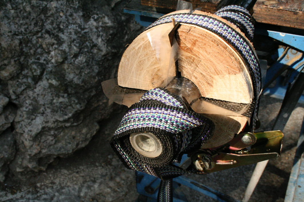
After the Sikaflex glue has dried (24 hours), the carbon sleeve is slid over the FTC tube and then coated with epoxy resin. The difficulty is to get this resin to penetrate all over the fabric. We used heat shrink tape wrapped over it for this. For drying, we placed two angles on the tube to ensure the rigidity of the tube during the polymerization. Then the whole was placed on a rotating bench (photo on the left) itself placed in a "solar oven" of our manufacture (polystyrene panels below and on the sides, all closed by a glass on the top). The tube therefore spun on the bench in full sun all day, plus one night without spinning.
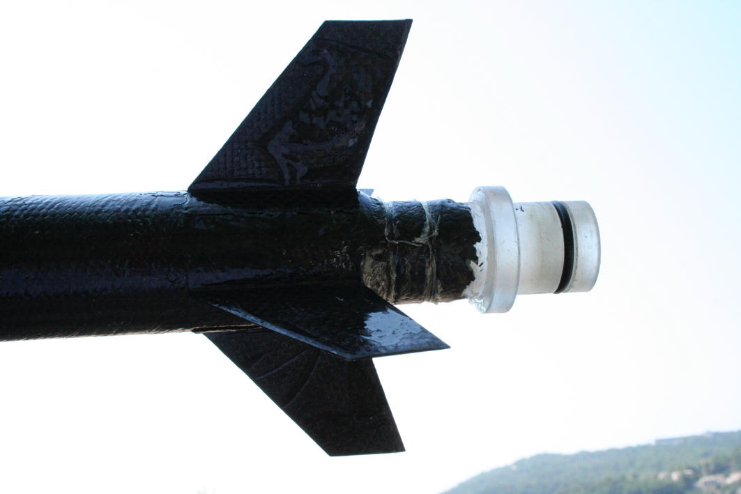
Then, we glued the fins, which required the creation of a wooden tool to be able to glue the 4 fins at once and keep them tight for 24 hours, while the epoxy was drying (Photo middle.
The photo on the left shows the ailerons in place as well as the nozzle.
 |
 |
 |
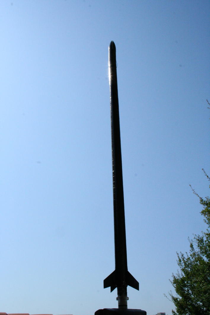
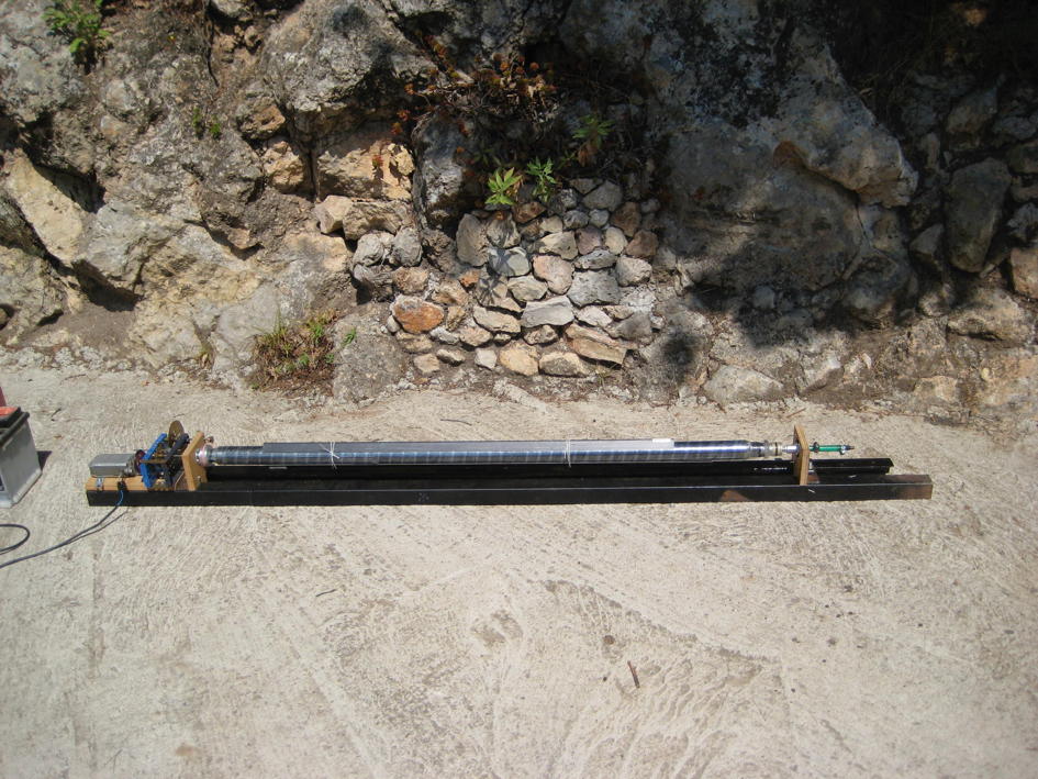
Opposite the life-size rocket. With a full weight of 850g, that is to say that in addition to the tank there were the electronics and the parachute surmounted by the cone, also in composite.
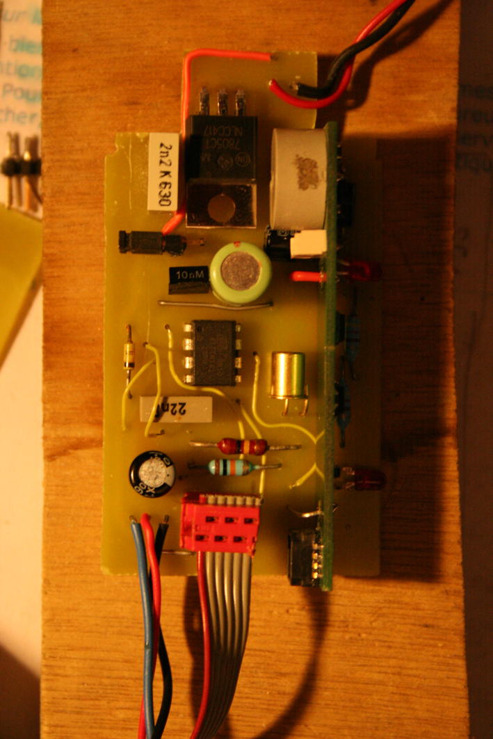
The electronics include an ATtiny45-based timer which drives a servo motor for opening the parachute and a Perfectflite A15k altimeter
 |
 |
|
View of electronics |
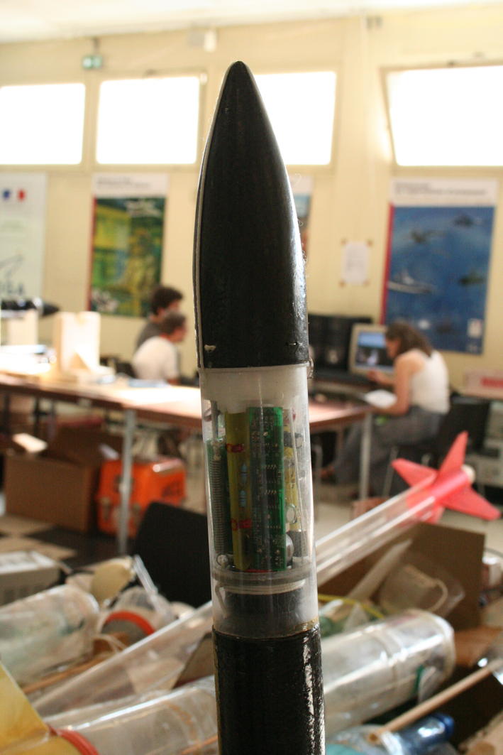
View of the electronic assembly and cone in which the parachute is housed |
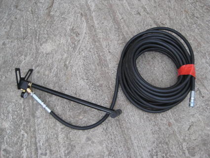
The pressurization system
For the pressurization, we used a Gehmann pump intended to fill the cartridges of compressed air guns. It can go up to 200 bars. For safety reasons, we add at the end of this pump a high pressure hose capable of holding 160 bars. This pipe is 20m long, which allows the rocket to be pressurized at a respectable distance.
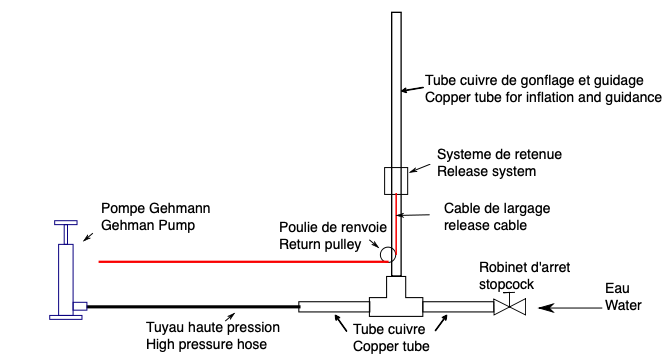
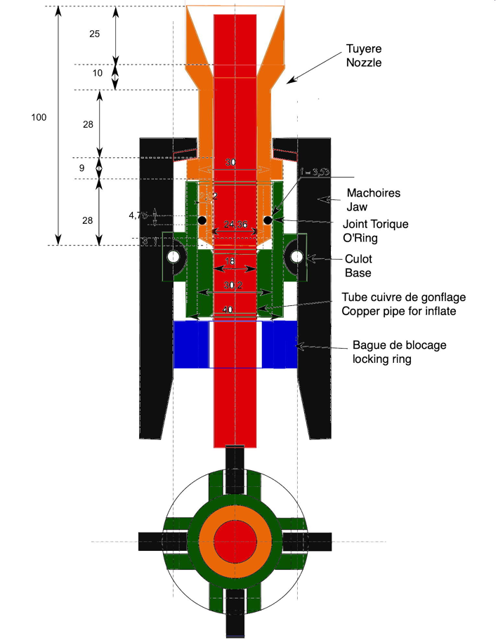
The Launcher
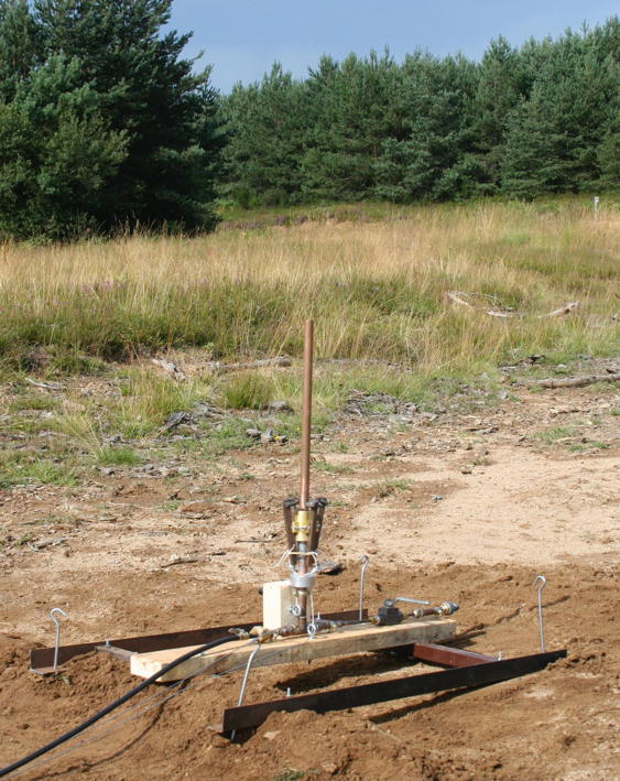
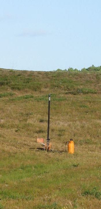
The photo opposite shows the ramp made according to the diagram above. the retaining system is identical to what I use for more classic rockets, namely jaws hold the nozzle in place thanks to a retaining ring which when pulled down allows the jaws to move away and thus release the rocket.
The launch
A first launch was carried out on 08/28/2009, in the precipitation. I did not yet have a water metering system and as the rocket is not transparent, I do not know how many liters of water we put. Due to a small leak, we had to throw at 15 bars. In short, the typical case of a poorly prepared launch, as a result, the parachute did not open, hence the crash. Fortunately, the altimeter survived and gave us an altitude of 146m.
|
|
|
|
|
Take off |
The electronic box (in gray) has been inserted a good centimeter on the tank? |
Electronics after the flight! But the altimeter, perpendicular to the main circuit, is intact. |