Recovery
Recovery systems
When you master the construction of water rockets more and more more efficient, you will quickly be tired of seeing your beautiful achievements destroyed after their first flight due to a sudden return to the ground. All naturally you will embark on the design of a recovery. To help you, here are some ideas.
The parachute on the rocket
The simplest system is to put the parachute directly under the cone. The risk then is that the cone does not fall to culmination. There are several reasons for this:
The speed of the rocket at culmination is non-zero, indeed the rocket
describes a parabolic trajectory and at the culmination it has a
direction parallel to the plane of the earth and its speed is not zero,
although the vertical component of this speed is indeed.
Under the effect of the acceleration at the start, the cone sinks on the
rocket and gets stuck definitively (yes definitely because his arrival
at floor won't help matters?)
To have a chance of success, 2 precautions are essential (but
unfortunately not necessarily sufficient):
Launch as vertically as possible so that the speed of the rocket is the
peak is as low as possible
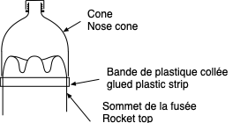
Place at the top of the rocket, just under the cone, a strip of plastic that will prevent the cone from sinking, as shown in the diagram below. When we flip the rocket, the cone must fall instantly. The parachute is housed in the cone, the lines will be glued to the top of the tank.
The aerodynamic flap
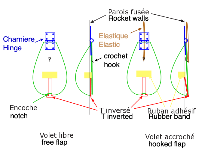
Briefly, it is based on maintaining the cone by a rubber band. even attached to an aerodynamic flap. This shutter is maintained along the body of the rocket by air speed, or by a micro shutter before the take-off of the machine. When the speed becomes low (so close to apogee), the flap opens and thus releases the elastic holding the cone. This is then ejected and the parachute can deploy.
Now let's see the details:
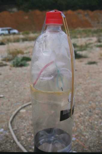 |
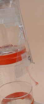
The cone and its fixationThe cone, classically the top of a bottle, rests on a rim made of a glued plastic sleeve (part yellowish in the photo). This sleeve prevents the cone from coming get stuck on the bottom of the bottle during acceleration, as one just saw it above. In the photo opposite, note the two rubber bands (red and green) stretched over the parachute to facilitate ejection of the cone. The two photos below show the fixing detail of these rubber bands. The elastic spider is fixed at using small plastic handles stapled to the cone. |
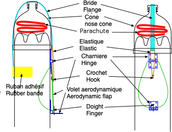 |
The drawing opposite details the principle: The cone is maintained by a set composed of a plastic flange (we can see a piece of it left of the cap on the photo above) and a rubber band (at right). This is hung on a small hook glued on the flap (it is just under the small piece of tape black). We see in the drawing that the flange is glued on one side (the one opposite the shutter) on the rocket using a piece of reinforced tape. A good idea is to pass this flange between the bottle and the cone blocking. On the other side we make a small loop in folding the end of the PET strip back on itself. A staple or a piece of tape will hold this loop closed. It is in this loop that we will pass the elastic The shutter, which is difficult to distinguish on the photo since it is made of PET like the bottle and therefore also transparent, is shown in green in the drawing. The fact that he either cut from a bottle, gives it an almost concavity identical to that of the bottle, so it is plaque perfectly on it. Its pear shape seems well suited to me, but don't ask me why, it's just a feeling. For fans of aerodynamics and conceptualization, I believe it there is plenty of research. This shutter is fixed, at the top, on the bottle at the by means of a plastic hinge for model making. The collage is not easy because these hinges are made of Polyamide (nylon) and nothing really sticks well. It is best to use either cyanolite plus reinforced adhesive tape. Realize very carefully this gluing because once glued, the shutter must be able to pivot very easily, so beware of excess glue. It is also not a bad idea to slide it under the cone locking sleeve. |
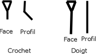 |
With a piece of wire (a paperclip will do the case), we realize the set "hook + finger" opposite. The hook will allow the elastic to hang on the shutter while the finger will keep the shutter closed before take off. These two pieces are then glued to inside the shutter using cyanolite and tape. The triangular parts of these two pieces have especially for aim to increase the bonding surface. For crochet, this triangular part is inside the shutter, while the right part crosses the shutter wall to protrude from 5 to 10 mm of the shutter. It is arranged at approximately 2/3 of the height of the shutter. The higher it is, the more elastic the cone holds can be stretched. For gluing, place the hook (or finger) on a piece of adhesive tape, place the cyanolite on the triangle then apply everything on the shutter. This method avoids put glue on the fingers. Just below the pane, paste the top of a another hinge on the rocket body. Also check that a once glued, it always rotates easily. Beforehand we will have taken care to make a hole 2 mm in diameter on the movable part of the hinge (therefore not glued to the body of rocket), so that you can insert your finger on the shutter. We can add on the mobile part of the hinge a mini aerodynamic flap to facilitate lowering when take off. |
How does it all work?
In the drawing above, the finger of the shutter passing through the bottom hinge hole, the shutter cannot open. So we can hold the cone by passing the flange over the plug and hanging the elastic on the hook of the shutter. The elastic must be enough taut so that the cone remains closed properly. Indeed, the elastic braces inside, the more the parachute tend to want to eject the cone (normal, they are there for that) .. When the rocket takes off, the aerodynamic force applied to the end of the hinge bottom, will press it against the body of the rocket, thus freeing the finger and the flap, which is pulled by the elastic, will tend to open. But the relative wind will oppose this opening, at least as long as it will be strong enough, in other words as long as the speed is sufficient. AT the apogee, where not very far from the apogee, the speed becoming low, the aerodynamic force on the flap becomes weaker than that of the elastic, the flap opens, releases the elastic and the strap, so the cone and the parachute.
Finally, don't forget to put a piece of string between the body of the rocket and the cone to retrieve this one.
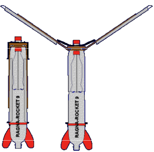
Below, an example of realization. On the left, the flap is blocked by the bottom hinge, before the flight.
On the right, the bottom hinge has been lowered and the shutter released. We can notice that the hook and the finger are made in one piece, which has the merit of stiffening the shutter.
Amélioration de ce système
|
|
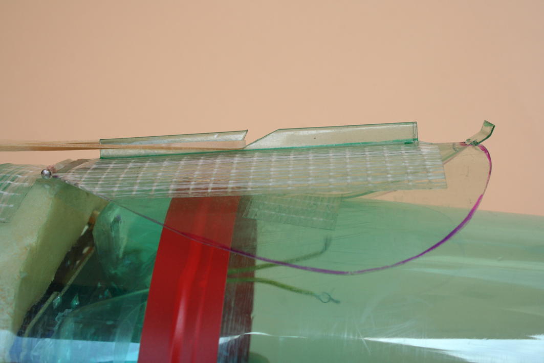
Another method of restraining the front flap take-off consists of using an inverted T in PET whose head hangs in a notch in the shutter as shown below. During the start, the relative wind will tackle the shutter against the bottle and thus release the T. This solution is both more economical and easier to produce than the previous for an often higher success rate. |
|
|
We see in this photo that the shutter is slightly off the rocket, but the inverted T (striped red) is preventing it from opening further. |
another improvement: the hook.
We have just freed ourselves from the metal finger, by the use of the inverted T, but there is still the hook that remains metallic. On the other hand, it happens that the shutter bends between the hinge and hook, if the elastic is too tight. To resolve these two problems, I opted for the following solution.
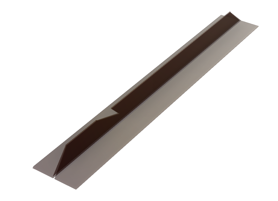
I am using a part, made from a rectangle of PET and which has the form below., on the left and on the rigth, glued on the flap.
Finally improvement for the cone ejection
We saw above that to facilitate the ejection of the cone, we placed an elastic cross member. It works well, except that rubber bands have a limited lifespan and they often need to be replace. To avoid this, the solution I have chosen is to place a PET crown inside the cone as shown in the photo below. It is necessary to calculate the diameter of this crown to that it deforms sufficiently but not too much when closing the cone.
The mechanical timer
Widely used on rockets built with the Polycarbonate tubes for neon tube protection (FTC). The timer is made from a spring motor, recovered from the small animated toys (TOMY brand among others).
The general principle is to keep in position a cone or a "catapult" using a stretched rubber band, as in the case of the aerodynamic flap. The elastic is kept in tension by a string which is hooked to a lug perpendicular to the axis of the engine. The motor is then reassembled to wind the string on the axle rotation, then lock the motor gears with a piece of plastic or a cable crimper, which will be torn off when taking off to start the motor rotation. When this one will have unfolded all the string, it will be released as well as the cone or the catapult. To limit the tension of the twine, therefore the torque on the axis of the engine, we can put baffles on the course of the string.
 |
On the top photo, the piston is held in low position by the elastic in the foreground which is fixed on the board on one side and on the motor shaft on the other. The middle photo shows the engine of the other side of the board On the third photo the elastic support has been released and we see a second elastic which propels the piston forward. It is this piston that will eject the parachute. |
I have never realized this type of recovery. I had bought toys with this type of motor, but all were spinning too fast. They were therefore not usable for this application. As also the aerodynamic shutter system works very well I did not persevere.
The electronic timer
Little used because the overall device is heavy. It is
indeed necessary to take a source of electrical energy, not only for the
timer itself, but above all for the trigger device. The latter can be a
servo motor, a electromagnet (very heavy), an electric motor or a
heating wire which cuts a nylon thread.
The preferred source of energy will undoubtedly be a LiPo battery which
is light.
For electronics we can use the famous NE555, or better still a microcontroller such as for example ATTiny25 / 45/85, which have the advantage of being able to easily pilot a servo motor.
There are very small and very light servo motors (9g and maybe less) and quite cheap.
Example of realization for a tube-based rocket FTC:
On the photos below, we see on the left the system holding the cone. The string seen on the left (not that of the foreground which is the attachment of the parachute) passes above the cone. It has an elastic at its end which hooks to the small lug that we see on the right. This is connected to the servo motor (center). At the end of the programmed time, the servo motor rotates 90 ° and the lug withdraws releasing the elastic and therefore the cone.
On the picture on the right we see the printed circuit with the microcontroller, here an ATTiny45.
The parachute
To calculate your size , you have to remember that the air resistance of a moving body is given by:
R = 1/2 *? * Cd * S * v 2 ,
where ? is the air density , Cd is a factor depending on the shape of the object, S is the surface of the master couple of this object (it is the surface of the projection of this object on a plane perpendicular to the displacement) and v speed.
The forces subjected to the parachute are on the one hand the weight P = m * g of the rocket and on the other hand the air resistance. In equilibrium we will have P = R so m * g = 1/2 * ? * Cd * S * v 2 . Depending on the descent speed that we allow ourselves, the calculation of the surface is therefore:
S = m * g / 0,5 * ? * Cd * v 2
Example: Consider a 150g rocket for which we want a descent speed of 7 m / s (25.2 km / h) and knowing that K = 0.5 * & lt; ? * Cd is about 1.2, this gives S = 0.15 * 9.81 / 1.2 * 7 2 = 0.025 m 2 i.e. a diameter of about 18 cm.
The graph below makes it possible to quickly find the parachute diameter according to the weight of the rocket and for a descent speed between 4 and 10 m/s.
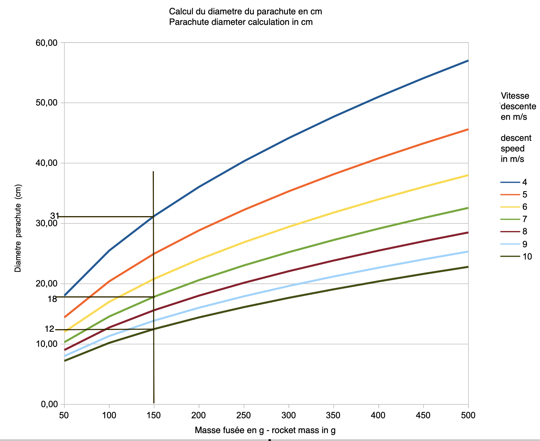
We see, for example, that for a rocket of 150g (vertical line) that If we want a descent speed of 7 m / s (green curve), it will take A parachute of diameter 18 cm about. But if we have a Parachute 31 cm from diameter, the descent speed will be 4 m / s and if the diameter is 12 cm then the speed will be 10 m / s.
What is the right descent speed?
If the speed is too weak and there is a little wind, we risk to walk a little more to recover its rocket.
If the speed is too high, the back to the ground will be more violent (But the water rockets are robust).
For my part, I try to have around 7 m / s. But it's just my opinion.
|
Making the parachute is simple. Take a leaf of light plastic, like the garment cover of the degreasing, at worst a garbage bag. Cut a square of side equal to the diameter of the parachute, fold it according to its diagonal then between the vertex of the obtained right triangle and the midpoint O of its hypotenuse. This last point being the future top of the parachute, fold back the plastic sheet 3 or 4 times between this vertex and the middle of the opposite side. We obtains a triangle whose base we cut such that the two long sides are equal to the radius of the parachute (according to the line AB in the figure opposite. We also cut the vertex of the triangle which allows to make a hole at the top of the parachute (essential otherwise the parachute is unstable). We unfolds the canopy of the parachute. For the lines, we cut 4 lengths of 3 times the diameter of the parachute, either in fishing line or in a little strong sewing thread, either in small string (to attaching meat for example). Each of these lengths is folded in half, which gives us 8 ends, so that no more than to tie on the canopy. For this, do on this canopy the eight marks where the fasteners will be made. Paste reinforced adhesive tape in these places, on each side of the attachment point. Make a small hole in the middle, pass the string and tie it. Once the eight ends are attached to the canopy, reunite the other ends using a piece of string or a ring. It only remains to attach it to the rocket, with adhesive tape for example. |
 |
These blades are mounted on a top of the bottle, itself fixed on an axis that passes through a small bottle and spins freely in this one. So the blade assembly, the blade articulation system, top of large bottle can rotate freely in relation to the body of the rocket, so that once the blades are unfolded, the setting rotation of the blades slows the descent of the assembly.
The photo opposite shows the realization that Hervé Brégent had made (whose site has unfortunately disappeared).
Gliding recovery
(space shuttle style), here with two schools, fixed wings or the deployable wings. For my part, I tried the second method. The description and the results obtained are on the page glider .